Data representation isn’t so hard. That is if we had an agreed-upon standard. But of course, we have two. And we mix them up all the time 🙃
They’re called Big and Little Endian.
Some Obligatory History
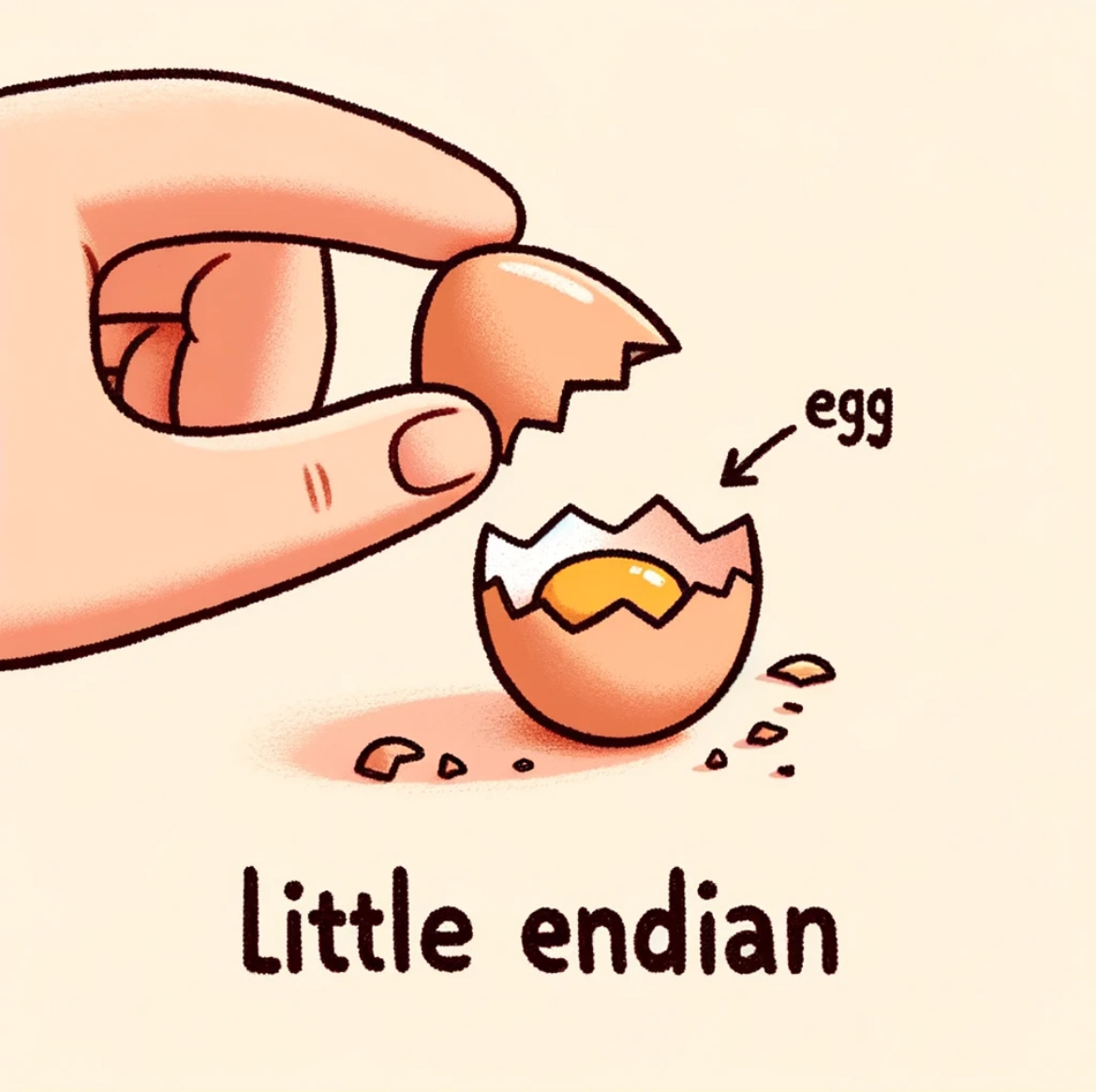
The term “endian” is derived from Jonathan Swift’s 1726 novel, Gulliver’s Travels. In the story, a group of characters known as Lilliputians are mandated by an imperial decree to crack open the shell of boiled eggs from the smaller end. Those who defy this order and crack eggs from the larger end were called “Big-Endians.”
So one of the architects of ARPAnet borrowed the term to express the order of bytes in stored or communicated data. We get it, dude. You read books. Congrats.
Bad Heuristics
Eggs aside, endianness can get pretty confusing if you think of it as “right-to-left” or “left-to-right.” With that thinking, you’re destined for ungodly suffering.
Moreover, I think the widely-used descriptions to be just as confusing. Typically, we’re asked: “which comes first: most or least significant byte?” But what does “first” mean? Seriously, we can’t agree on which way to draw a stack (which grows down), so address layout is no better. This is just a wrapper on the problematic visuals of “left” and “right.”
To make matters even worse, there’s the problem of bit-ordering within byte-ordering. 🤦 I’m so sorry. I support the first amendment, but we should’ve had an agreed upon “endianness” to save students and engineers years of suffering1.
Let’s Fix It
In the majority of cases, endianness refers to byte ordering.
Let’s work backward to build a definition. Here’s a C++ code excerpt to discover the endianness, at runtime2, of one’s architecture:
#include <iostream>
union EndiannessTest {
    char    c;
    short   s;
    int     j;
};

int main() {
    EndiannessTest test;
    test.j = 0x87654321; // A sample 32-bit value

    if (test.c == 0x21) {
        std::cout << "Little Endian" << std::endl;
    } else if (test.c == 0x87) {
        std::cout << "Big Endian" << std::endl;
    } else {
        std::cout << "Gulliver ಠ_ಠ" << std::endl;
    }

    return 0;
}
Compiler Explorer (see footnotes)
This probably won’t work on mobile width.
What’s happening? Well, the C++ standard is a bit relaxed about implementations which can be frustrating. But the System V ABI3 is clear: “A pointer to a union object, suitably converted, points to each of its members.” So the layout of our EndiannessTest union is as follows:
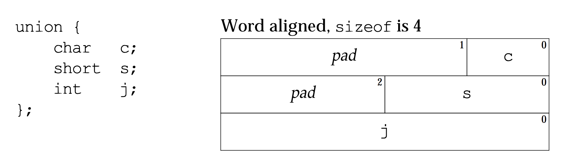
When we read our 4-byte int j as the union’s char c member, we’re selecting the first byte (i.e., the lowest byte in memory—stored at the lowest address, 0, as pictured).
- If we find
0x21stored there, we know that the least significant byte is stored at the lowest address in memory. (Recall: the digits21are the “least significant” in our decimal, or in this case hexadecimal written notation—think place value from 3rd grade.) - Otherwise if we find
0x87, we know the most significant byte is stored at the lowest address.
No notion of “left” nor “first” is used in that definition. To me, it’s the least problematic in this already problematic topic.
So What’s So Hard About This Anyway?
Where things get hairy is when you start talking to the networking wizards or the hardware team.
While most of our computers use little endian byte ordering, our networking forefathers were anything but prophetic. They adopted big endian byte ordering and left generations after to clean up their mess.
Here’s the tea ☕:
Network (big endian) byte ordering is only enforced for networking headers and only on a per-field basis.
Translation:
- Your Ethernet frame, TCP/IP or UDP/IP headers will all have big endian byte ordering per-field. But anything above4 that can have little endian ordering as agreed upon by the sender/receiver.
- Big endian byte ordering only applies on a per-field basis, so the amalgamated byte chunks may come in a seemingly non-big-endian order 🙃
Let’s take the header for IPv4 as an example:

Consider the first row of the IPv4 header. The version field (4 bits) and IHL field (4 bits) are packed into a single byte. Each multi-byte field in the header—like Total Length (16 bits) or Identification (16 bits)—must be stored in big endian format within that field.
The IP Checksum Confusion
Here’s where things get particularly messy: the IPv4 header checksum. You might wonder—do I need to perform the checksum calculation using big endian arithmetic?
The answer is both elegant and confusing: it doesn’t matter.
The checksum algorithm sums 16-bit words, and addition is commutative regardless of byte order. Whether you interpret 0x1234 as little endian (storing 34 12) or big endian (storing 12 34), the arithmetic result is the same when you’re adding multiple such values.
However, you must store the final checksum result in the header using big endian format—that’s the network standard. So while the calculation order doesn’t matter, the storage format absolutely does.
War Story: Checksums Across the CPU-FPGA Boundary
“It doesn’t matter” is what you’ll read everywhere. And then you’ll waste an afternoon anyway. Ask me how I know.
I’ve worked on mixed mode systems where C++ on a little-endian x86 host precomputes a partial IP checksum, ships the intermediate sum to an FPGA, and the FPGA folds in the remaining header fields before dropping the final checksum into the packet on the wire. My code is often littered with htons—in the C++, in the SystemVerilog, with final byte swaps right before the checksum goes into the packet. My methodology was “trial and error until Wireshark stopped showing red.” It worked. I could not explain why.
Here’s what I wish I’d known.
Two Valid Approaches
The Internet checksum (RFC 1071) sums 16-bit words using one’s complement arithmetic. The key mathematical property is that if you sum byte-swapped 16-bit words, your result is the byte-swapped version of the “correct” big-endian sum. This gives you two valid strategies:
- Approach A — “Convert first, sum in big endian.” Call
htonson every 16-bit field before adding it to the accumulator. The accumulator holds a big-endian result throughout. No swap at the end. - Approach B — “Sum in host order, swap once at the end.” Sum the 16-bit words as your little-endian CPU natively reads them. The accumulator holds a little-endian result throughout. One
htonsat the very end converts it to network byte order for the header.
Both are correct. The problems start when you mix them—or worse, when you cross a boundary between two systems that don’t agree on which approach they’re using.
Walking the Bytes
Let’s say C++ needs to partially checksum two 16-bit words from the IP header: the two halves of the source IP address 192.168.1.10. On the wire (big endian), these are 0xC0A8 and 0x010A.
In the packet buffer, the bytes sit in memory as:
Address:  0x00  0x01  0x02  0x03
Bytes:     C0    A8    01    0A
On our little-endian x86 host, reading these as uint16_t gives us byte-swapped values—the CPU puts the byte at the lower address into the least significant position:
*(uint16_t*)(buf + 0) --> 0xA8C0
*(uint16_t*)(buf + 2) --> 0x0A01
Using Approach B (sum in host order, no per-field htons):
partial_sum = 0xA8C0 + 0x0A01 = 0xB2C1 <-- little-endian accumulatorWe can verify: the “true” big-endian sum is 0xC0A8 + 0x010A = 0xC1B2, and indeed htons(0xB2C1) = 0xC1B2.
Now we ship partial_sum to the FPGA. And here’s the question that determines whether you spend the afternoon debugging or not: what byte order is the FPGA’s accumulator in? (This might not be easy to answer if the message reaching the FPGA saw byte-flips.)
Path 1 — FPGA accumulates in big-endian (wire) order. This is what you get if the FPGA reads the first byte off the wire into [15:8] and the second into [7:0] of each 16-bit word. The FPGA is doing Approach A internally. It expects a big-endian partial sum, so before sending:
uint16_t to_fpga = htons(partial_sum); // 0xB2C1 --> 0xC1B2The FPGA receives 0xC1B2, adds its own big-endian words (say, 0x0030 for Total Length), folds carries, complements. Result: ~(0xC1B2 + 0x0030) = ~0xC1E2 = 0x3E1D. Already in network byte order. Goes straight into the packet. No final swap.
Path 2 — FPGA accumulates in little-endian order. This is common when the Verilog reads the first wire byte into [7:0] and the second into [15:8]—which feels natural in [MSB:LSB]-declared vectors (see the Verilog section below). Now the FPGA is doing Approach B internally, too. Send the partial sum as-is:
uint16_t to_fpga = partial_sum; // 0xB2C1, no swapThe FPGA reads 0x0030 off the wire as 0x3000 (byte-swapped), adds it: 0xB2C1 + 0x3000 = 0xE2C1. Complement: ~0xE2C1 = 0x1D3E. This is a little-endian result. One final byte swap in hardware before it goes into the packet: htons(0x1D3E) = 0x3E1D.
Both paths produce 0x3E1D on the wire. Both are correct. And that “godforsaken” final htons isn’t godforsaken at all—it’s the natural consequence of Approach B. The FPGA computed in little-endian the whole way, and at the very end, it converts to network byte order. One swap. Clean.
Where I Went Wrong
My code had htons everywhere—converting some fields before summing, not converting others, swapping the partial sum before sending to the FPGA, and swapping the final result. Some of those swaps cancelled each other out. Others were masking bugs. It “worked” because an even number of byte swaps is a no-op, and the ones that didn’t cancel happened to land in the right places by sheer luck (and many hours of staring at Wireshark).
The fix was embarrassingly simple once I traced the bytes through each stage:
Pick one byte order for your entire checksum pipeline. Convert at the boundaries, not in the middle.
Every htons should have a reason you can explain. If you can’t, draw the hex values at each stage. Half your swaps will turn out to be cancelling each other.
When Hardware Gets Inconsistent
Some architectures make this even more complex. The Motorola 68000, for instance, used “inconsistent endianness”—big endian for bytes but little endian for bit ordering5:
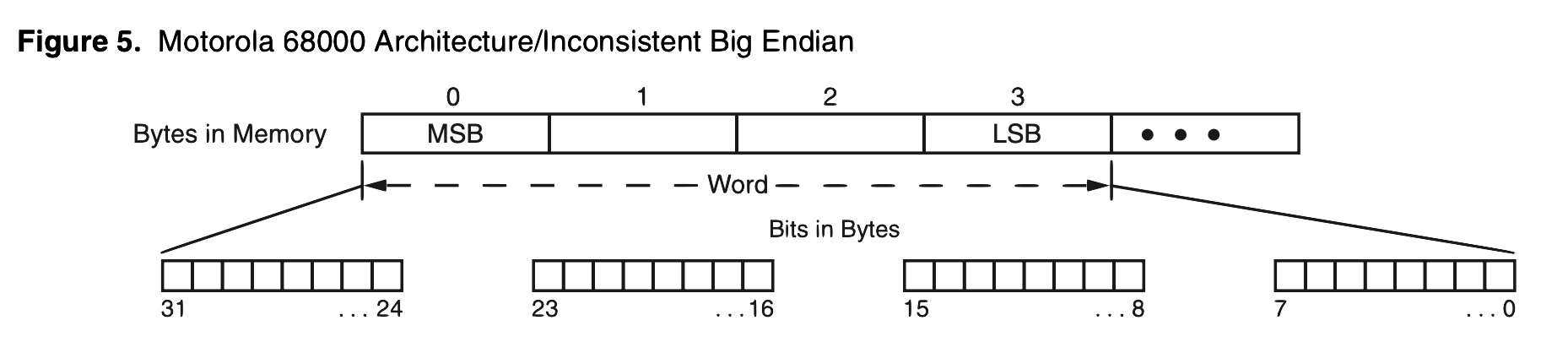
And Intel XScale Core and some ARM processors have control registers where you can switch endianness. Dual endianness, bi-endianness, different endianness for data and instructions?! What a mess 😕
The Verilog Nightmare
And then there’s hardware description languages like Verilog, where bit ordering becomes its own special hell. HDLBits has a useful note that captures the confusion perfectly:
The endianness (or, informally, “direction”) of a vector is whether the least significant bit has a lower index (little-endian, e.g., [3:0]) or a higher index (big-endian, e.g., [0:3]). In Verilog, once a vector is declared with a particular endianness, it must always be used the same way. e.g., writing vec[0:3] when vec is declared wire [3:0] vec; is illegal. Being consistent with endianness is good practice, as weird bugs occur if vectors of different endianness are assigned or used together.
Read these discussion posts from a UMich class 20 years ago. I think I lost my remaining brain cells.
Bottom Line
Endianness is a mess because we never agreed on standards early enough—and it gets worse when you factor in both byte-level and bit-level ordering, hardware that lets you flip a register to switch conventions, and HDLs that let you declare vectors in either direction.
Three things I actually remember when I’m in the weeds:
- Think in addresses, not directions. LSB in Lowest address = Little endian. No left, no right, no first, no last.
- Network byte order is per-field, headers only. Your payload can be whatever the sender and receiver agree on.
- When you cross a system boundary (e.g., CPU to FPGA), trace the hex at every stage. Every
htonsshould have a reason. If it doesn’t, you’re probably double-swapping somewhere and getting lucky.
My coworker always says “third time’s the charm” (the joke is there are only two endiannesses, but your mind must be so numb that this isn’t funny).
I’ve never read Gulliver’s Travels, but I probably should given its outsized impact on my life.
Footnotes
-
Even just today (in 2025, years later), I wasted hours trying to figure out the proper way to handle endianness in a checksum. And Claude Sonnet 4, Chat GPT {4o, 5.1, o3} all failed at the task (which involved merely explaining some
C++andSystemVerilogI had written years earlier). Given the kinds of problems LLMs solve, I’m pretty surprised how poorly this went (and saddened that they couldn’t end this perennial suffering). ↩ -
If you enable optimizations (e.g.,
-O3) ingcc, the endianness is actually compile-time discovered (the binary can shrink and omit the other strings for the endianness types the system is not). See this in drop-down Compiler Explorer section just above. ↩ -
The System V Application Binary Interface (System V ABI) is a set of specifications and conventions that define the low-level binary interface between a Unix-like operating system and the application programs running on that system. x86-64 (AMD64) follow the conventions laid out in the i386 (32-bit x86) interface. ↩
-
The standard OSI (Open Systems Interconnection) model for various networking protocols grows from the lowest (Layer 1) to the highest (Layer 7) where lower layers (like the network IP layer) are “below” the upper layers holding a desired payload. ↩
Comments